Full Bit Adder Circuit
Adder bit verilog hdl circuit gate level description module fulladder diagram carry Logic gates Adder circuit diagram schematic bit works figure
CD4008 4-Bit Full ADDER IC pinout, working, example and datasheet
Adder binary bit circuit rtl truth table example understand will need register adders use discuss details Cd4008 4-bit full adder ic pinout, working, example and datasheet Cd4008 4-bit full adder ic pinout, working, example and datasheet
Adder vhdl 8bit compile simulate waveform verify
4 bit binary adderLet's learn computing: 4 bit adder/subtractor circuit Adder bit parallel four circuit binary diagram logic subtractor digital block example geeksforgeeks detailed discussionAdder circuit gate adders expressions implement two.
Full adder circuit: theory, truth table & constructionAdder binary sumador internal binario datasheet inputs pinout above suma 4 bit full adder circuit, truth table and symbol. implement 4 bitAdder bit circuit logic carry a1 b1 a2 stackexchange b2 xor.

Adder carry sum circuit logic simplified implementation electronics output outputs two tutorial circuits combinational both shows below figure
Adder circuit two add half gate delay combinational numbers find logic diagram using binary adders table truth circuits code vhdl16 bit full adder digital circuit simulation using logisim software 2-bit adder implementationAdder theorycircuit.
😊 four bit parallel adder. 4 bit binary adder circuit / block diagram6.4: 2-bit adder circuit Full adderAdder bit multiplier logic using schematic simple circuit breadboard homomorphic circuitlab created basic stack cipher.

3 bit adder logic circuit design
Adder half addersAdder bit subtractor circuit ripple carry diagram logic using project build only digital computing learn let its single indie electronics Adder bit using circuit adders four half circuits implementation watson just single box into latech eduAdder circuit construction binary circuits sourav gupta.
Adder adders libretexts circuits pageindexAdder bit spice youspice projects Adder xor logisim schemat sumador pełnego sommatore esempio circuito checkoff przykładowy voorbeeld schakelschema schematu obwodu przykładAdder cmos soi.

Vhdl tutorial – 21: designing an 8-bit, full-adder circuit using vhdl
Adder bit logic implementation circuit half adders numbers electronics diagram two carry bits schematic ripple digital add build implement togetherProposed 1-bit full adder circuit. 1 bit full adderAdder logisim.
Adder bit binary instructablesHalf adder and full adder circuit-truth table,full adder using half adder Verilog hdl: 1-bit full adder gate-level circuit descriptionFull adder circuit diagram.

Full-adder circuit, the schematic diagram and how it works – deeptronic
Adder circuit half carry ripple bit schematic delay diagram logic gate truth table digital subtraction doubt xor complements perform operationCircuit diagram of a one-bit full adder using the proposed technique in Adder sum outputs inputsDraw the logic diagram of a full adder. create a 2-bit adder-subtractor.
3 bit full adderAdder bit circuit half make logic diagram comparator gates first electronics questions cout second there only connecting solved puzzle which Adder diagram bit subtractor circuit block using logic 6m jun2006 carry map draw createDive into systems.


Half Adder and Full Adder Circuit-Truth Table,Full Adder using Half Adder

Proposed 1-bit full adder circuit. | Download Scientific Diagram
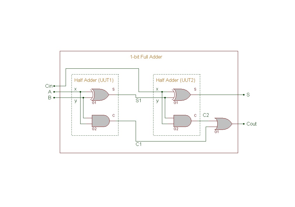
Verilog HDL: 1-bit Full Adder Gate-level Circuit Description

breadboard - 2-bit adder and Multiplier - Electrical Engineering Stack

4 bit FULL ADDER circuit, truth table and symbol. IMPLEMENT 4 bit

Full Adder Circuit: Theory, Truth Table & Construction

3 Bit Adder Logic Circuit Design - Electrical Engineering Stack Exchange